Automated Cladding
Kristen Stapper
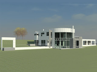 In the first project, it was rather difficult adding cladding to all of the walls, so I worked on some methods within a program using Revit API to automatically accomplish this task.
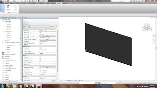
I began with a straight wall. The Ids of the wall and the cladding element (at the corner of the wall) were brought into the program and set as variables.
The only parameter values needed from the wall were its length and height.
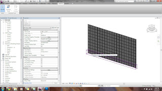
Revit has a LinearArray class, which was used to fill the wall. The number needed in the array was determined from 2 variables. One used the wall length divided be the clad width, and the other used the height of both and performed the same calculation.
An array along the length was created first. Next, this array is stored in a variable and used to create the second array, filling the height.
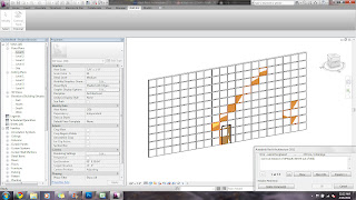
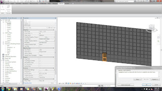
An issue with the array is that all of the elements are stored in their array groups. If some elements are unwanted, i.e. those over the door, then attempting to delete them causes sporadic problems with other elements across the wall as shown.
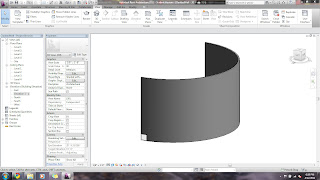
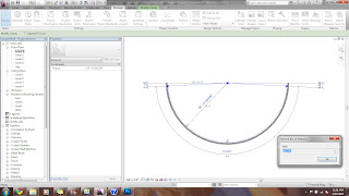
I attempted to also run this for a curved wall. Revit has another class called the RadialArray that would need to be used in this example. Unlike the LinearArray, which uses a location point, the RadialArray uses an angle in radians. The issue with this class becomes apparent during execution. Arrays work from the element's center, and arraying from the cladding's center causes the array to miss its wall host, deleting the elements. To fix the code, the user would need to open the class, which is not available.
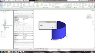
Getting the wall and cladding Ids for the program
Other methods were tried to fix the RadialArray. I tried to change the cladding's location point before the array to the wall's center, but since it cannot leave its host, it was unsuccessful.
A smaller wall host was put at the curved wall's center with cladding. The idea was that when it is arrayed, the cladding would have the curved wall to host into; however, this was also unsuccessful.
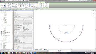
The current solution for curved walls is to manually array the length, since the rotation location point of the cladding can be moved to the wall's center.
Then, either manually array the height using the first array, or select all elements of the array and input them into the program to allow it to array the second one.
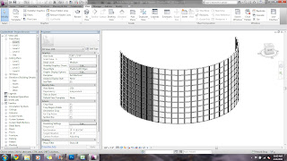
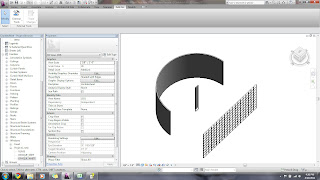
Finished wall
Another method was tried eliminating arrays.
Instead, two for loops are used, one for length and one for height. They are set to run to the length of the wall's length and height from the variables already calculated in the other program.
The wall's location point is found and set, which is where the cladding knows to begin filling in. These location points are XYZ coordinates.
With this method, the elements remain as individuals and not as a part of a group, so deleting individual cladding elements is not a problem when replacing them with doors or windows.
A step further adds an if statement to the code that causes the loops to jump over the location points of door or window ids that are sent to the program, eliminating the need to go back and delete unwanted cladding.


